Few mechanical paintball markers match the legendary battlefield longevity of the Tippmann 98 Custom. Yet after years of cycling unregulated liquid CO2 or 850 PSI compressed air, even this cast-aluminum workhorse will eventually develop a relentless hiss down the barrel or along the receiver seam. In our field tests and match clinics maintaining rental fleets and scenario markers, performing a complete tippmann 98 valve rebuild is the single most effective procedure to cure down-barrel air leaks, eliminate recocking sputter, and restore factory 285 FPS velocity consistency without replacing the entire power tube assembly.
Key Technical Takeaways: Tippmann 98 Valve Rebuild
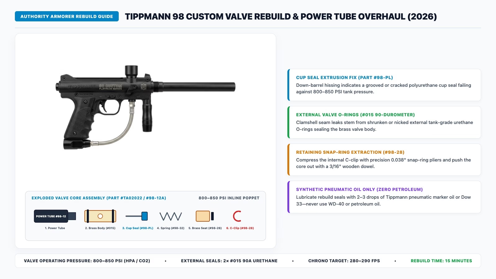
A successful tippmann 98 valve rebuild requires isolating whether high-pressure gas (800–850 PSI) is escaping past the internal polymer cup seal (#98-PL) down the barrel or bypassing the two external #015 90-durometer urethane valve body O-rings along the clamshell seam. Always extract the brass valve core using a 3/16-inch wooden dowel and precision snap-ring pliers to avoid scoring the brass valve seat (#98-26).
800–850 PSI
HPA or Liquid CO2
≈ 27.7 lbf
Pneumatic + Spring
2× #015 (90A)
Urethane Tank O-Rings
3.2 mm / 4.5 ms
Poppet Dwell Impulse
- Down-Barrel vs. Seam Leak Rule: Air hissing out the muzzle indicates an extruded internal cup seal (#98-PL) or pitted brass seat (#98-26); air venting out the trigger frame or receiver seam points to worn external #015 valve body O-rings.
- Wooden Dowel Extraction Protocol: Push the brass valve body out of the composite power tube (#98-12) using a 3/16-inch wooden dowel inserted through the front nozzle—never use a steel screwdriver.
- Fatal Lubrication Error: Never apply petroleum-based gun oil, WD-40, or thick automotive grease inside the valve chamber. Use only 2 to 3 drops of synthetic pneumatic marker oil.
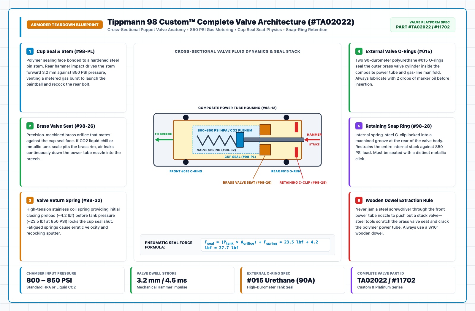
Fluid Dynamics & Mechanics: How the Tippmann 98 Inline Poppet Valve Works
Unlike modern low-pressure spool-valve tournament markers operating at 110 to 135 PSI, the Tippmann 98 Custom utilizes an unregulated high-pressure inline blowback drivetrain. Whether you run CO2 or compressed air (HPA), full tank output pressure (800 to 850 PSI) travels directly through the stainless steel braided gas line into the brass valve chamber inside the composite power tube. When planning a tippmann 98 valve rebuild, armorers must account for four mechanical and thermodynamic forces:
- Hydrostatic Poppet Sealing Force: Inside the brass valve housing (Part #TA02022 / Platinum #11702), the polymer cup seal (#98-PL) is held shut against the brass valve seat (#98-26) by both the coiled stainless valve spring (#98-32) and incoming tank pressure. Across an effective sealing orifice area of approximately 0.0276 sq inches, the total closing force is governed by: Fseal = (Ptank × Aseat) + Fspring ≈ (850 PSI × 0.0276 in2) + 4.2 lbf ≈ 27.66 lbf. Over thousands of cycles, this continuous 27.7-pound mechanical load stamps a deep circular groove into the face of the polymer cup seal.
- Hammer Kinetic Impulse & Valve Dwell (4.5 ms): When you pull the trigger, the sear releases the rear drive spring, propelling the steel rear hammer forward to strike the protruding pin stem of the cup seal. The hammer’s kinetic energy (Ek = ½ m v2 ≈ 1.85 Joules) knocks the cup seal forward 3.2 mm for approximately 4.5 milliseconds. Approximately 65% of the vented gas rushes forward through the power tube nozzle to fire the paintball at 280–290 FPS (≈11.2 Joules muzzle energy), while 35% vents backward to recock the hammer against the sear.
- Adiabatic CO2 Cryogenic Embrittlement: When firing liquid CO2 rapidly, phase-change vaporization drops internal brass valve temperatures below −20°F (−29°C) according to Joule-Thomson cooling (ΔT = μJT × ΔP). This thermal shock shrinks Buna-N rubber and causes aged polyurethane cup seals to fracture like glass.
- Spring-Rate Fatigue & Machine-Gunning: If the internal valve spring (#98-32) loses its free length (1.12 inches nominal) due to corrosion or compression set, or if tank pressure drops below 550 PSI, the backward blowback pulse becomes strong enough to push the hammer past the cup seal stem without reaching the trigger sear—resulting in runaway “machine-gunning” sputter.
Master Diagnostic Matrix: Tippmann 98 Valve Leak & Failure Lookup Table
Before ordering replacement parts or splitting the clamshell receiver, pinpoint the exact faulty component in your paintball marker leak diagnosis using our master armorer lookup table below:
| Acoustic / Mechanical Symptom | Faulty Valve Part (#ID) | Root Cause / Physics Mechanism | Armorer Rebuild Fix | Replacement Part / Kit |
|---|---|---|---|---|
| Continuous Hiss Down Barrel / Breech Most common valve failure |
Cup Seal Stem (#98-PL) & Brass Seat (#98-26) | 27.7 lbf static seat load extrudes polymer face, or brass flakes embed in seal rim | Extract C-clip, replace cup seal (#98-PL), polish or replace brass valve seat (#98-26) |
Check Amazon Check eBay |
| Air Venting at Receiver Seam / Trigger External manifold bypass |
External Valve O-Rings (2× #015 90A) | Outer urethane O-rings on brass valve body pinched during installation or dried out | Install 2 fresh 90-durometer urethane #015 O-rings (see paintball O-ring sizing chart) |
Check Amazon Check eBay |
| Runaway Machine-Gunning / Sputtering Hammer fails to catch sear |
Valve Return Spring (#98-32) & Rear Bumper | Weakened valve spring stays open too long (>6 ms) or swollen rear bolt O-ring drags | Replace valve spring (#98-32), inspect sear catch lip, and oil rear hammer O-ring |
Check Amazon Check eBay |
| Cracked Power Tube / Stripped Banjo Structural housing failure |
Complete Valve & Power Tube (#TA02022) | Over-torquing the braided hose nut or Cyclone Feed banjo fitting cracks polymer | Drop in a pre-assembled Complete Valve & Power Tube assembly (#TA02022 / #11702) |
Check Amazon Check eBay |
| Velocity Stuck Below 230 FPS Restricted gas transfer |
Internal Valve Washer (#98-27) & Velocity Screw | Swollen internal rubber washer Caused by petroleum oil blocking the forward gas port | Flush brass body with isopropyl alcohol, install fresh seal kit, lube with synthetic marker oil |
Check Amazon Check eBay |
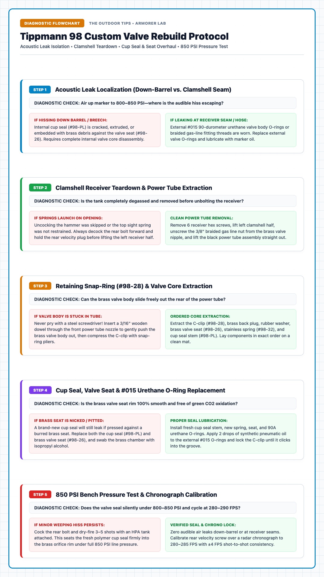
Step-by-Step Execution: How to Perform a Tippmann 98 Valve Rebuild
Whether you own an original two-piece clamshell 98 Custom or a modern Split-Receiver Platinum Series (which shares the identical internal valve architecture with the Tippmann Cronus and Tippmann A-5), follow this exact five-phase armorer sequence to execute a clean valve core overhaul:
Phase 1: Depressurization & Clamshell Receiver Teardown
Before touching a hex key, make the marker 100% mechanically and pneumatically safe:
- Remove Hopper, Paint, and Air Cylinder: Unclamp your gravity hopper, verify the breech is clear, and unscrew your HPA or CO2 bottle (if your tank pin is binding, consult our guide to safely empty a paintball tank at home).
- Decock the Internal Hammer: Point the marker in a safe direction and pull the trigger once or twice to vent residual gas and release the rear hammer forward. Opening the clamshell with the rear hammer cocked will launch the main drive spring across your workbench.
- Remove Receiver Body Screws: Lay the marker flat on its right side (with the “98 Custom” nameplate facing up). Using a 1/8-inch and 5/32-inch Allen wrench, remove the six receiver body bolts and the two grip frame screws.
- Lift the Left Receiver Shell: Place your thumb over the rear velocity plug and top sight latch (to capture the tiny sight spring), then lift the left aluminum receiver shell straight up. Verify that the orange flexible ball detent stays seated in its slot.
Phase 2: Braided Gas Line & Power Tube Extraction
With the internal drivetrain exposed, isolate the composite power tube (#98-12) from the linkage:
- Disconnect the Steel Braided Hose: Hold the brass valve inlet fitting stationary and use a 3/8-inch open-end wrench to loosen the swivel flare nut at the top of the stainless braided gas line. (If your marker has a Response Trigger or Cyclone banjo fitting attached to the power tube port, unscrew the banjo bolt carefully.)
- Extract the Linkage Arm, Front Bolt, and Hammer: Lift out the silver cocking linkage rod, the front delrin bolt, the rear steel hammer, the drive spring, and the plastic spring guide pin.
- Slide Out the Power Tube: Lift the black composite power tube straight out of the right receiver shell.
Phase 3: Valve Core Removal & Snap-Ring Extraction
The brass valve cylinder sits recessed inside the rear bore of the composite power tube:
- Push Out the Brass Valve Housing: Insert a 3/16-inch wooden dowel or brass rod through the front nozzle of the power tube and push the brass valve body gently out the back. Never use a flathead steel screwdriver, which will gouge the internal brass seat or crack the polymer tube wall.
- Compress the Retaining C-Clip (#98-28): Look into the rear of the brass valve body to locate the internal spring-steel retaining ring (C-clip). Place your thumb over the opening to catch spring-loaded parts, squeeze the two C-clip eyelets together using precision 0.038-inch internal snap-ring pliers, and slide the clip out of its groove.
- Layout the Internal Valve Stack in Order: Tip the brass housing onto a clean microfiber towel and tap out: (1) the brass back plug, (2) the rubber back plug washer, (3) the brass valve seat (#98-26), (4) the inner valve seat rubber seal (#98-27), (5) the coiled stainless valve spring (#98-32), and (6) the cup seal and pin stem (#98-PL).
Phase 4: Ultrasonic / Alcohol Cleaning & Seal Replacement
Every internal surface must be 100% free of metallic scale and degraded elastomer bits before installing new seals during your power tube overhaul:
- Swab the Brass Valve Chamber: Dip a cotton swab in 91% isopropyl alcohol and scrub the inside of the brass valve cylinder until all greenish-black CO2 oxidation and old oil sludge are gone.
- Inspect the Brass Valve Seat Rim (#98-26): Examine the raised circular lip of the brass valve seat under a bright bench light. If the brass lip is dented, scratched, or corroded, replace the brass seat along with the cup seal—a nicked brass rim will slice a brand-new cup seal on the first shot.
- Install New Cup Seal, Spring, and Washers: Drop the new cup seal (#98-PL) into the brass cylinder with its metal pin stem pointing out the rear hole. Place the new valve spring (#98-32) over the cup seal head, followed by the brass valve seat (raised lip facing the cup seal), the rubber washer, and the rear plug.
- Lock the Retaining C-Clip (#98-28): Compress the new C-clip with your snap-ring pliers, press the rear plug inward against spring tension, and seat the C-clip into the internal machined groove until you hear a crisp metallic click. Verify with a dental pick that the clip is seated 360 degrees around the groove.
- Replace External #015 Urethane O-Rings: Roll two fresh 90-durometer polyurethane #015 O-rings into the outer grooves of the brass valve body. Apply 2 drops of synthetic pneumatic marker oil across the O-rings and slide the brass valve back into the composite power tube until the gas inlet hole aligns with the bottom port.
Phase 5: Reassembly, 850 PSI Seat-In & Chronograph Verification
Reinstall the power tube, front bolt, linkage arm, and rear hammer into the right receiver shell, ensuring the flat side of the rear velocity nut rests flush against the receiver wall:
- Torque Receiver Bolts Evenly: Tighten the 3/8-inch braided gas line nut snug (do not over-torque past 35 in-lbs), place the left clamshell half on top, and tighten the six receiver screws in a crisscross pattern.
- Perform the 3-Shot High-Pressure Seat-In: Cock the marker first, then attach an 800–850 PSI HPA tank. If you hear a faint whisper of air down the barrel initially, fire 3 to 5 dry shots in a safe direction. The 850 PSI impact seats the fresh polymer cup seal tightly against the brass seat orifice, sealing the valve completely silent.
- Calibrate Velocity Over a Chronograph: Head to the test range and fire 10 shots over a radar paintball chronograph. Adjust the rear velocity screw (counter-clockwise to increase FPS, clockwise to decrease) to lock in 280–285 FPS (or 275–285 FPS if running a Tippmann 98 Flatline barrel).
ASTM F1776 High-Pressure Retaining Ring & Eye Safety Mandate
Under ASTM F1776 paintball marker safety standards, the internal retaining C-clip (#98-28) restrains up to 850 PSI of direct pneumatic force inside the brass valve chamber. Never air up a disassembled power tube outside of the bolted aluminum clamshell receiver, and never reuse a bent or sprung retaining ring. Always wear ANSI Z87.1 impact-rated safety glasses when compressing snap rings, and install an ASTM-certified barrel blocking sock before airing up your rebuilt marker.
Essential Workbench Tools & Kits for a Tippmann 98 Valve Rebuild
Having the right snap-ring pliers and genuine OEM polyurethane seals turns a frustrating 45-minute struggle into a 15-minute routine overhaul. Here are our field-tested workbench essentials:
| Tool / Rebuild Component | Armorer Role in Valve Overhaul | Technical Specification | Direct Purchase Links |
|---|---|---|---|
| OEM Tippmann 98 Valve Rebuild Kit | Replaces internal cup seal, valve spring, brass seat, washers, and C-clip | Includes #98-PL, #98-32, #98-26, #98-28 & #015 O-rings |
Check Amazon Check eBay |
| Precision Internal Snap-Ring Pliers | Compresses and seats the #98-28 internal retaining C-clip cleanly | 0.038-inch (1.0 mm) fine straight tips |
Check Amazon Check eBay |
| Complete Pre-Assembled Valve (#TA02022) | Drop-in 2-minute swap when the composite power tube or brass body is cracked | Factory assembled Power Tube + Valve Core (#11702) |
Check Amazon Check eBay |
| Synthetic Pneumatic Marker Oil | Lubricates external #015 urethane O-rings and rear blowback hammer seal | 100% Non-petroleum, urethane-safe viscosity |
Check Amazon Check eBay |
Video Demonstration: Extracting & Rebuilding the Tippmann 98 Valve
Watch this hands-on workbench walkthrough demonstrating how to safely push the brass valve assembly out of the composite power tube, compress the retaining C-clip, and replace the internal cup seal and O-rings:
Final Armorer Verdict: Component Rebuild vs. Complete Valve Swap
If your composite power tube (#98-12) is structurally intact with uncracked banjo threads, performing an internal tippmann 98 valve rebuild with an $8 OEM seal kit (#98-PL cup seal, #98-32 spring, and dual #015 90-durometer urethane O-rings) is the gold-standard armorer choice. However, if the black plastic power tube nozzle is cracked or the internal brass housing is deeply corroded from years of liquid CO2 abuse, skip the individual seal teardown and drop in a factory pre-assembled Complete Valve & Power Tube unit (#TA02022 / #11702).
To extend the lifespan of your newly rebuilt valve by 5+ years, transition from liquid CO2 to regulated 800 PSI HPA and follow our off-season paintball marker storage protocol by adding 3 drops of synthetic pneumatic oil into the ASA before storing your marker uncocked.
Frequently Asked Questions About Servicing Tippmann 98 Valves
Why does my Tippmann 98 still hiss down the barrel right after a tippmann 98 valve rebuild?
Two factors cause a post-rebuild barrel hiss: first, a brand-new polyurethane cup seal (#98-PL) often requires 3 to 5 dry-fired shots at full 800–850 PSI tank pressure to conform against the brass valve seat (#98-26). Make sure you cock the rear bolt before airing up the tank so the rear hammer is not pressing on the valve pin. Second, if the leak persists after 5 shots, the brass valve seat rim itself is nicked or installed backward (the raised circular ridge must face the flat polymer face of the cup seal).
Are all Tippmann 98 Custom valves identical across older and Platinum Series markers?
The internal valve components—specifically the #98-PL cup seal, #98-32 valve spring, #98-26 brass seat, #98-28 C-clip, and #015 external O-rings—are 100% interchangeable across classic Tippmann 98 Custom, Custom Pro, ACT, Platinum Series, A-5, X7 Classic, and Cronus markers. However, note that older Model 98 markers manufactured prior to 2002 used a single-O-ring brass valve body, whereas modern #TA02022 / #11702 valves use dual external #015 O-rings.
Can I use standard black Buna-N O-rings on the outside of the brass valve body?
While 70-durometer black Buna-N #015 O-rings will seal temporarily on compressed air (HPA), they absorb liquid CO2 and swell up to 30% in volume, causing them to extrude and shred inside the power tube. Always install 90-durometer polyurethane (clear or white tank-grade) #015 O-rings on the exterior of the Tippmann 98 valve body for permanent CO2 and HPA durability.
How do I get a stuck brass valve out of the black plastic power tube without damaging it?
If swollen O-rings have wedged the brass valve inside the composite power tube, drop 4 to 5 drops of isopropyl alcohol or synthetic marker oil into the rear of the tube and let it soak for 2 minutes. Then insert a flat-ended 3/16-inch wooden dowel through the narrow front nozzle of the power tube and tap the back of the dowel lightly against your workbench to push the brass cylinder out the rear.
Can I rebuild the Tippmann 98 valve without removing the power tube from the gun?
No. The brass valve core exits exclusively through the rear bore of the composite power tube, which is blocked by the rear hammer and main drive spring when installed in the receiver. Furthermore, the 3/8-inch braided gas line fitting threads directly into the bottom of the brass valve body, locking it inside the power tube until the hose is unscrewed.
How often does a Tippmann 98 Custom need a valve rebuild?
Markers running clean regulated HPA (800–850 PSI) and oiled every 3,000 shots typically run 25,000 to 40,000 rounds (3 to 5 years of recreational play) before needing a new cup seal. Markers running liquid CO2 without an anti-siphon tube experience severe cryogenic thermal cycling and typically require a tippmann 98 valve rebuild every 8,000 to 15,000 shots.